Cheap DIY servo tester
19 October 2009I have some cheap servos lying around, with no datasheet available… since I want to use them for a future robotics project I had to get the information I need one way or another…
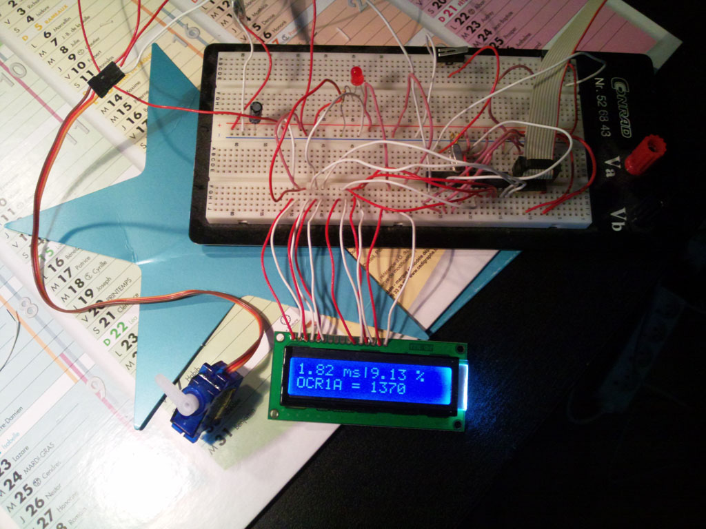
Ladies and gentlemen, let me introduce you the DIY servo tester I made:
So first of all how do servos work? it's simple, really, most of them have 3 pins: VCC, GND, and PWM Hook the VCC pin to 5v, the GND one to 0v, and the PWM pin to a device that generates a 50hz pwm signal (a square signal with a variable duty cycle) with the smallest duty cycle handled by the servo the angular position is at its maximum position clockwise, and with the highest duty cycle handled by the servo the angular position is at its maximum counterclockwise.
My problem was to find those values!
As you can see on the picture the length of the pulse was 1.82ms which is 9.13% (duty cycle) of a 50 Hz period (20ms). Since I use the built-in pwm function provided by the atmega168 (the microcontroller I use) the OCR1A value and the top value associated (ICR1) I can generate an accurate square signal. Some internal counter starts at 0 with the output at 5v, when it reaches ORC1A the output goes to 0v, and when it reaches ICR1, the counter resets, and the output goes to 5v again and so on…
Anyway, there are to buttons, one to make it go CW, decreasing the OCR1A value, one to make it go CCW, increasing the OCR1A values… now all I have to do is read the values when it won't go any further in both directions…
I'm going to post the source code and the schematics as soon as possible !
October 23rd, 2009 at 12:33 am
The target economy must reward people for having full ownership of possessions punishing acts of arson and property damage with deterring severity. ,