Project One: a clock with 7 segment displays and an Atmel Atmega8 µC
18 September 2006This is my first project with Atmel's microcontrolers…
it's an idea i had to learn how to use digital I/Os, internal timer, interrupts,…
The hardware/software may not be very optimised, but the clock is quite accurate! :p
1. The timer
How does it work?
the timer is increased by one every P clock ticks (P is the prescaler, its value can be 1,8,64,256,1024), and it generate an interrupt each time it overflows (255 to 0)
Now we have timer_interrupt_frequency = F_CPU/(P*256)
thus with a 11,0592Mhz crystal, and P=64, the timer interrupt frequency is: 11059200/(64*256) = 675Hz (yeah exactly 675, not 675,00000000001 nor 674.9999999999999999999999, … 675!)
That means that 1 second = 675 interrupts
we just need to increase the seconds every 675 interrupts, the minutes every 60 seconds, the hours every 60 minutes, …
2. the 7 segment displays
how to drive 7*4= 28 leds ?
remember, we do not have 28 i/o pins! the solution? Charlieplexing!
the 4 cathods (one per display) of each segments are linked together to 7i/o pins and the 4 common anodes are linked to 4 i/o pins
and we make the whole thing go so fast that human eye sees the four displays on at the same time(remember pov "article")
3. the electronical part
schematic
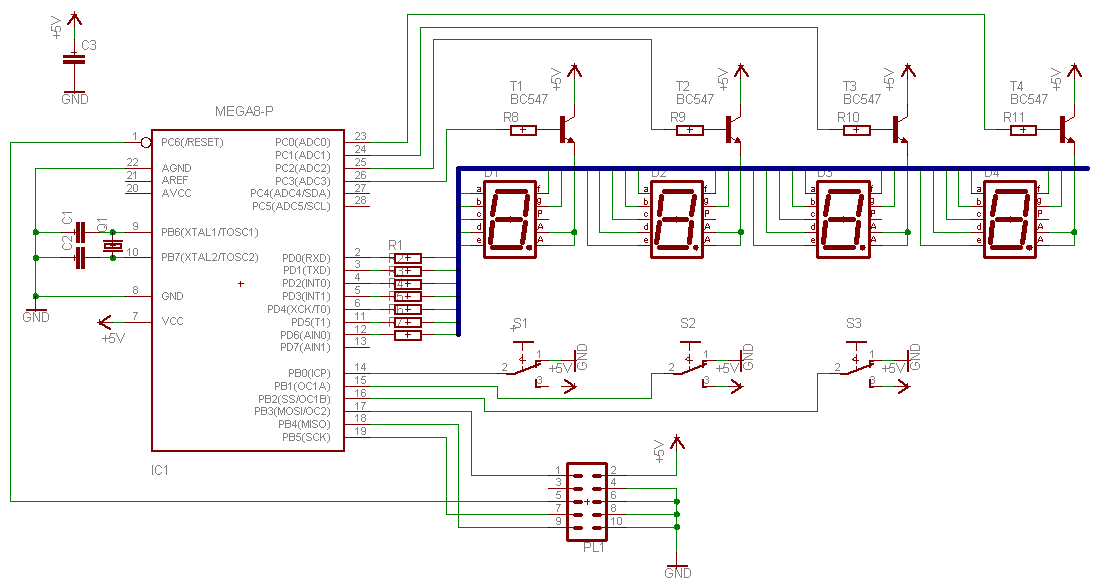
4. the source code
#define F_CPU 11059200UL // 11,0592mhz#include <avr/io.h>#include <avr/interrupt.h>#include <stdbool.h>#define STOP_TIMER TCCR0 &= 0b11111000#define START_TIMER TCCR0 |= 0b00000011 // prescaler = c/64typedef volatile unsigned char BYTE;typedef volatile unsigned int WORD;BYTE minutes=0;BYTE seconds=0;BYTE hours=0;WORD Interrupts=0;bool s=false;bool h=false;bool m=false;unsigned char segs[]={0b00111111,0b00000110,0b01011011,0b01001111,0b01100110,0b01101101,0b01111101,0b00000111,0b01111111,0b01101111};ISR(TIMER0_OVF_vect){Interrupts++;// at 11,0592mhz with a 'Clock/64' prescaler, 675 interrupts = 1 sec!if (Interrupts == 675){if(++seconds>=60){seconds=0;if(++minutes>=60){minutes=0;if(++hours>=24){hours=0;}}}Interrupts = 0;}}void ConfigureDevice(void){cli(); // mask interruptions_SFR_BYTE(DDRD)=0b11111111;_SFR_BYTE(DDRC)=0b00001111;_SFR_BYTE(DDRB)=0b00000000;TCNT0 = 0x00;START_TIMER;TIMSK |= _BV(TOIE0);sei(); // unmask interruptions}int main(void){// format: 8 8 : 8 8// segment: 8 4 2 1// segment is used to select each 7segments display one after the other (with pov there's no need to have 4 seven bits ports)// 8=0b00001000;4=0b00000100;2=0b00000010;1=0b00000001// btw, it's possible to use only one pin from c port with the 8th from b port (2 bits = 4 combinations) but then we'll need some extra elecronic demux partunsigned char segment=1;unsigned char portval=0;unsigned char temp=0;ConfigureDevice();hours=0;minutes=0;seconds=0;while(1){m=(PINB&0b00000100)==0?0:m;h=(PINB&0b00000010)==0?0:h;if((PINB&0b00000001)!=0 && (PINB&0b00000010)!=0 && !h){h=true;seconds=0;Interrupts=0;if(++hours>=24){hours=0;}}temp=PINB&0b00000100;if((PINB&0b00000001)!=0 && (PINB&0b00000100)!=0 && !m){m=true;seconds=0;Interrupts=0;if(++minutes>=60){minutes=0;}}switch(segment){//segs is inverted to use with common anode 7 segments displays (up to 300mA sinking current)case 1:/*xx:xV*/ portval=~segs[minutes%10];break;case 2:/*xx:Vx*/ portval=~segs[minutes/10];break;case 4:/*xV:xx*/ portval=~segs[hours%10];break;case 8:/*Vx:xx*/ portval=~segs[hours/10];break;}_SFR_BYTE(PORTC)=0;_SFR_BYTE(PORTD)=portval;_SFR_BYTE(PORTC)=segment;segment=(segment<<1)>8?1:segment<<1;}}
Download this code: avrclock.c
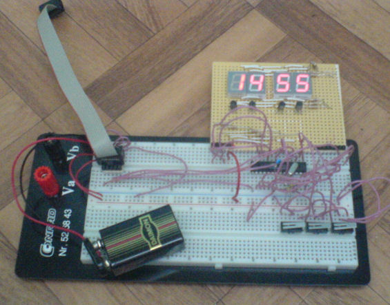
5. the final result